A
Accommodation
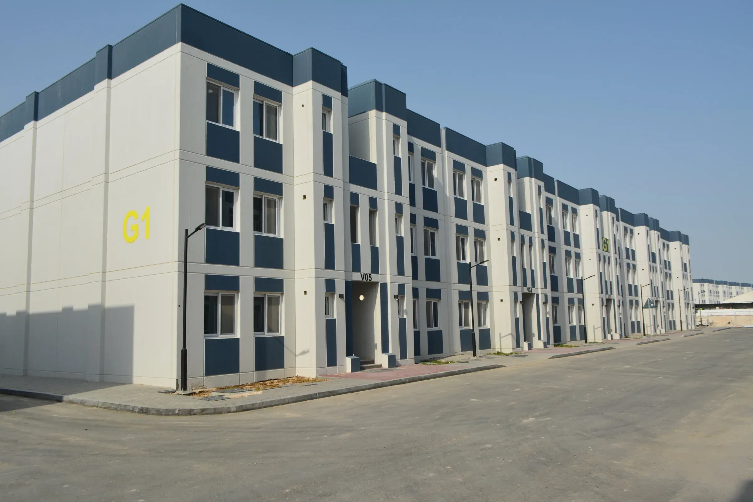
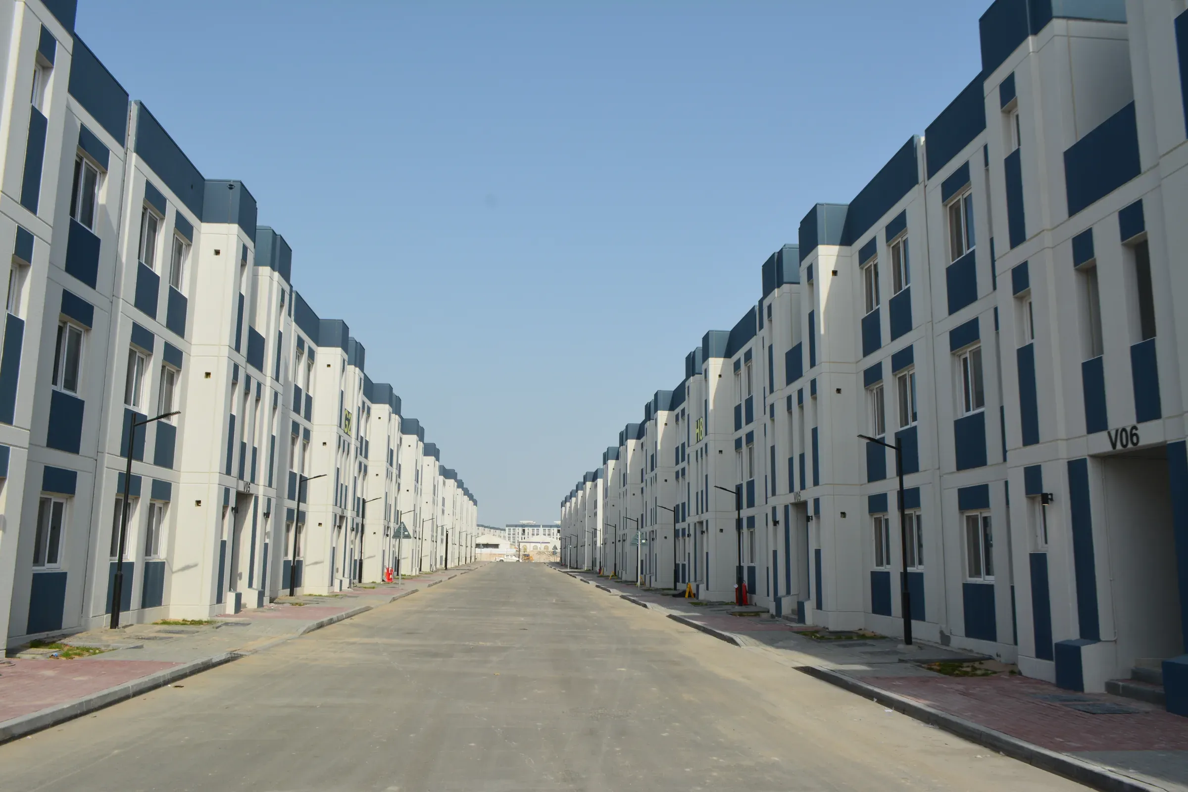
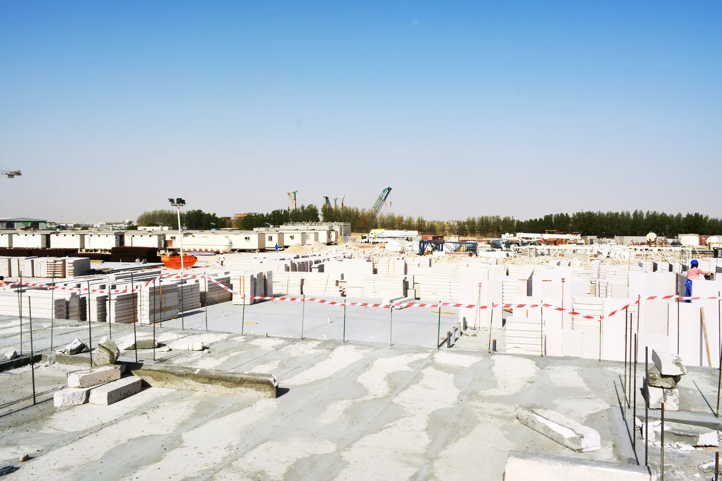
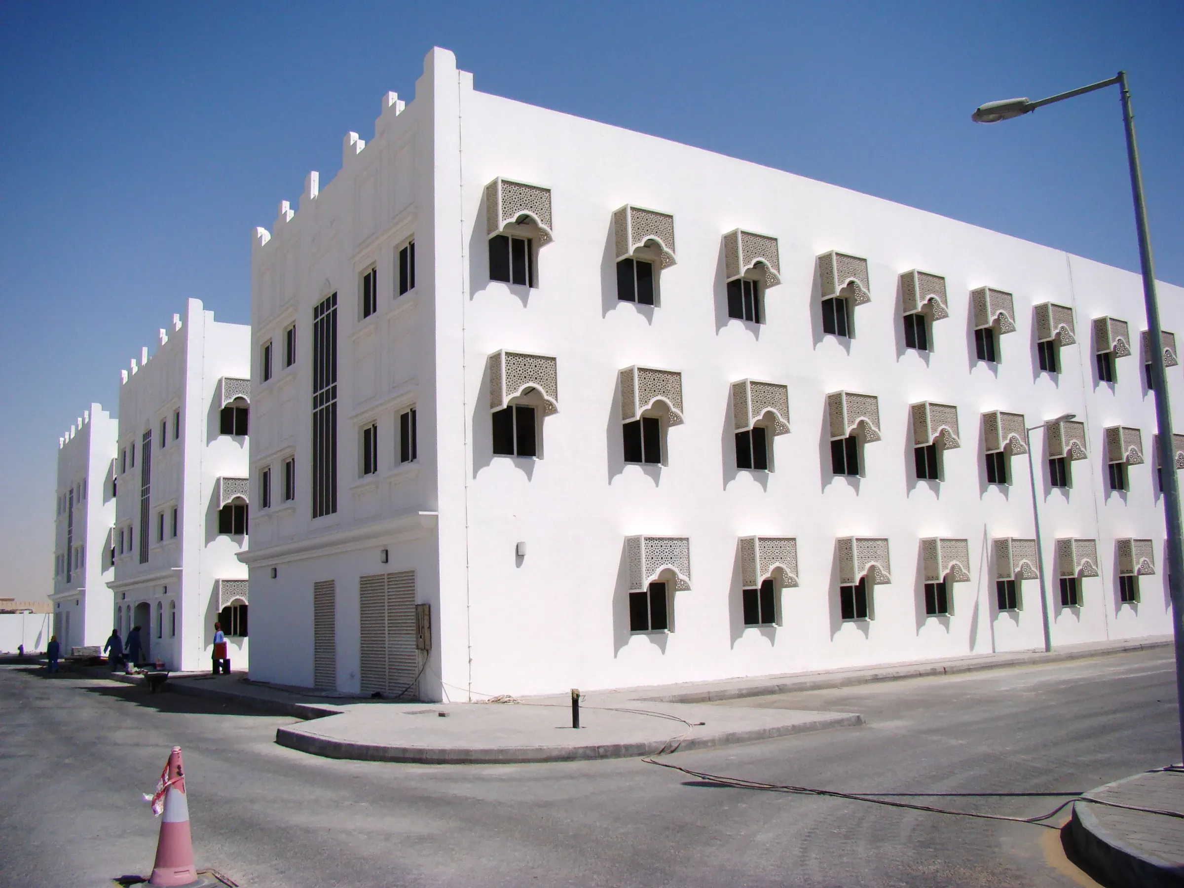
Complete AAC accommodation buildings up to G+4: wall panels, floor and roof slabs, no RC columns or beams.
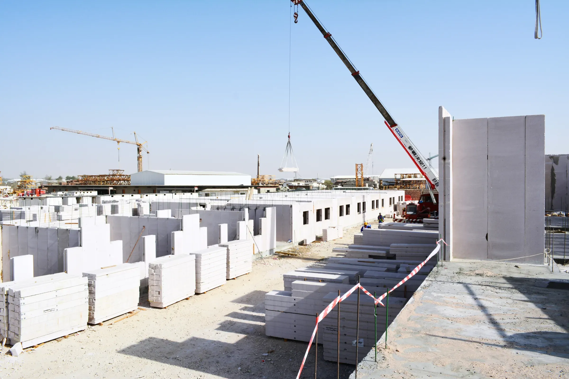
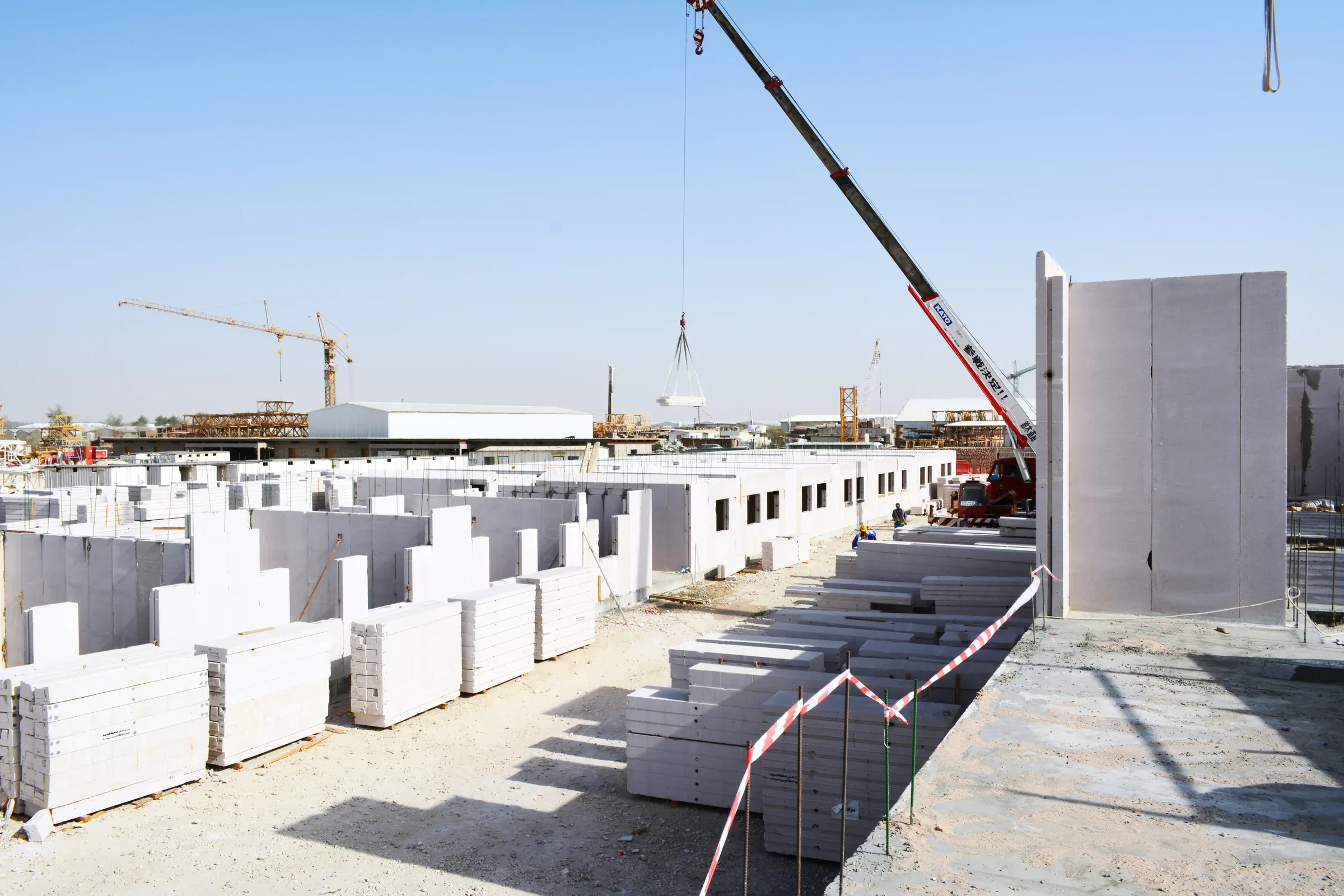
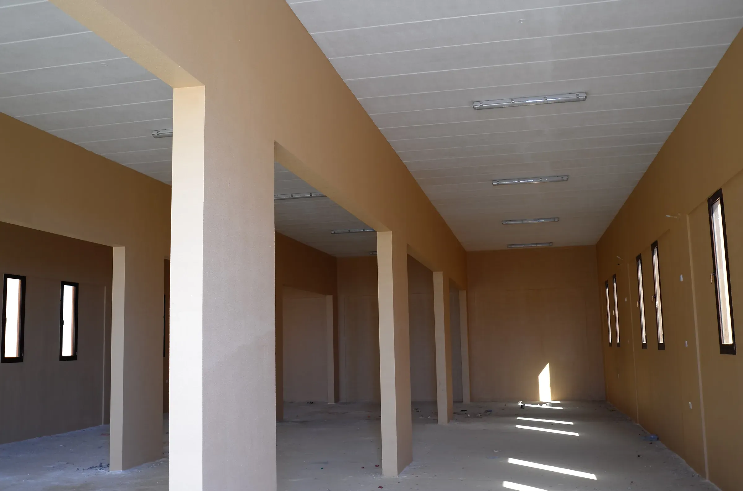
The full load-bearing AAC system from the autoclave to the site: wall panels, floor and roof slabs and lintels that combine into a complete precast structure. The system needs no RC columns or RC beams and is finished with coating and paint.
Vertical wall panels, floor and roof slabs and lintels combine into a complete precast, load-bearing structure on an RC raft or grid-beam foundation, and can contribute up to 20 LEED points.
Three reinforced AAC components on an RC ring beam and foundation cast by the main contractor.
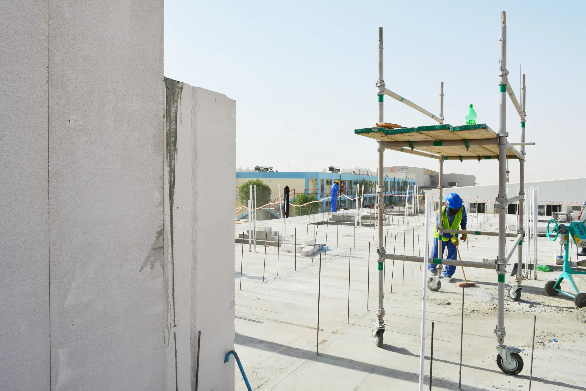
Full storey height, up to 6 m long and 600 mm wide, 100 to 300 mm thick. Load-bearing external and internal walls.
Reinforced slabs up to 6 m, simply supported on the AAC walls or on concrete or steel beams.
Over doors and windows, cut to the opening, same material as the wall.
Cast by the main contractor to our coordination drawings. A raft 20 to 45 cm or grid beams under the walls is usually enough.
Density 650 kg/m³, minimum compressive strength 4.0 MPa, thermal conductivity 0.12 W/m·K, 40 dB STC at 100 mm and 48 dB at 200 mm. The full technical data sheet is in the catalogue.
The system is sold and installed as six sub-systems. Each has its own brochure with details, drawings and projects, sent on request.
Complete AAC accommodation buildings up to G+4: wall panels, floor and roof slabs, no RC columns or beams.
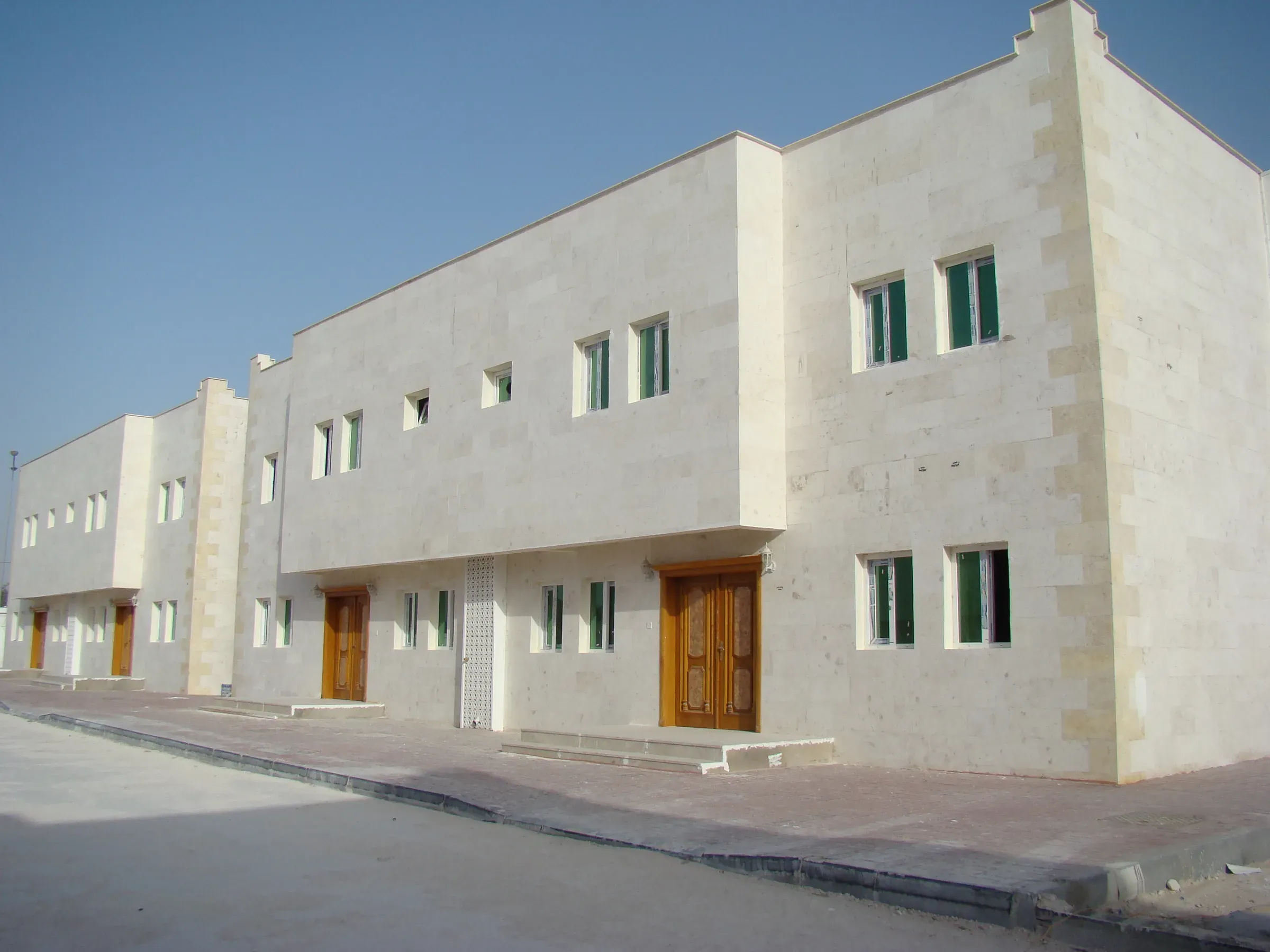
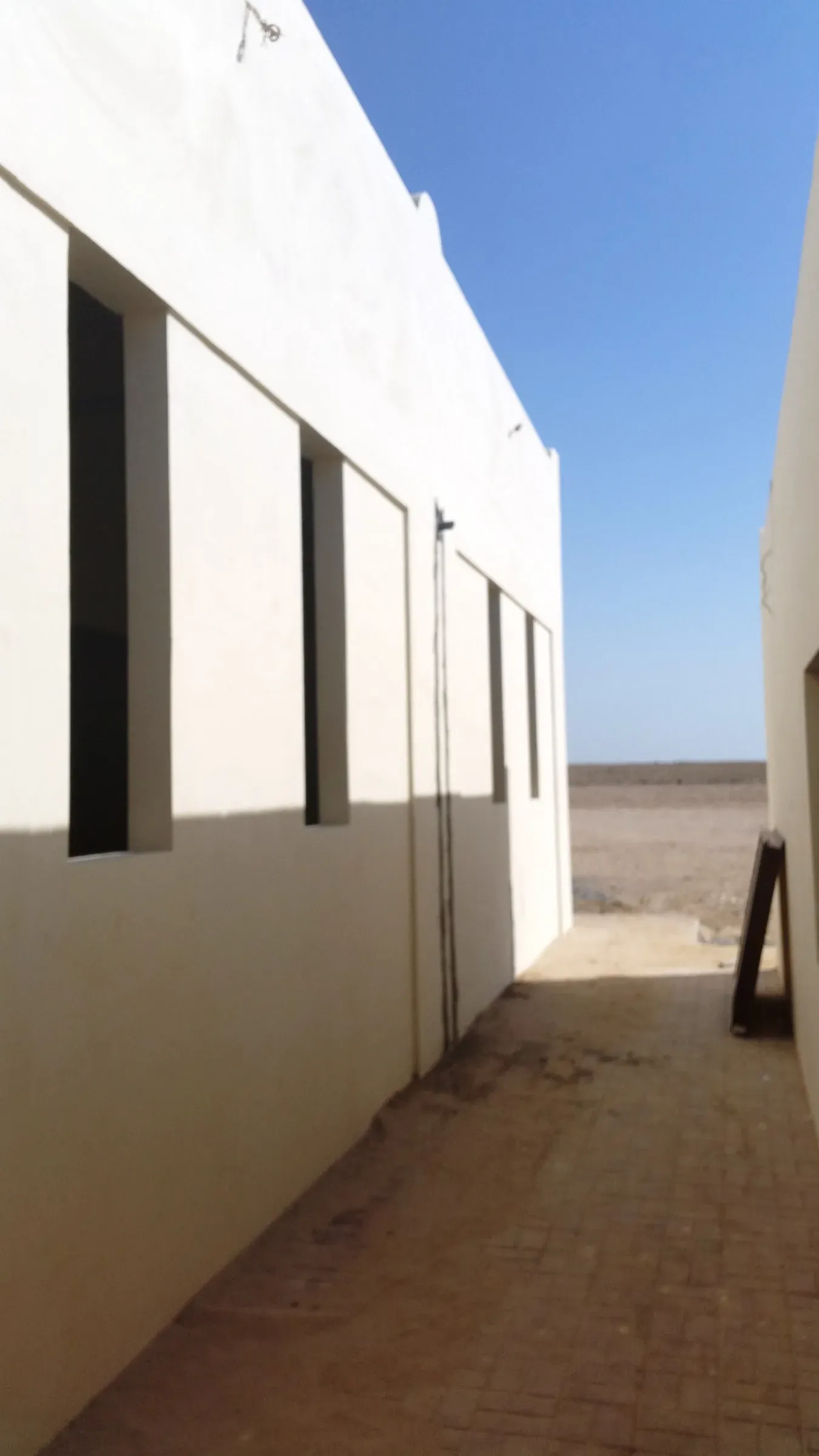
Villas, compounds, hotels, schools and mosques built in AAC walls alone or in the full walls-and-slabs system.
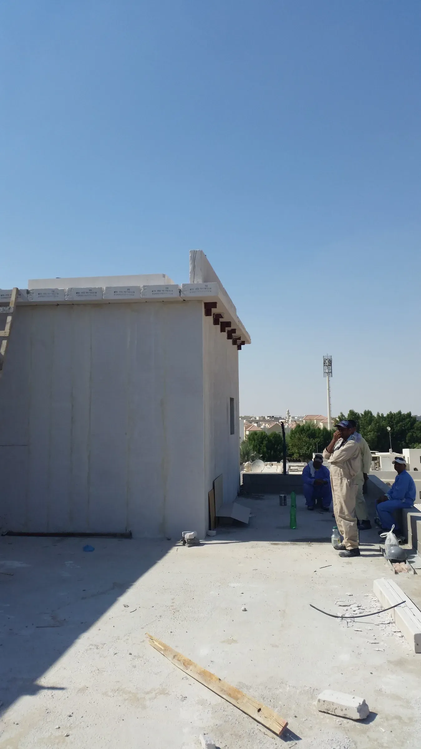
Extra floors and extensions on existing buildings: light AAC walls and slabs that the old structure can carry.
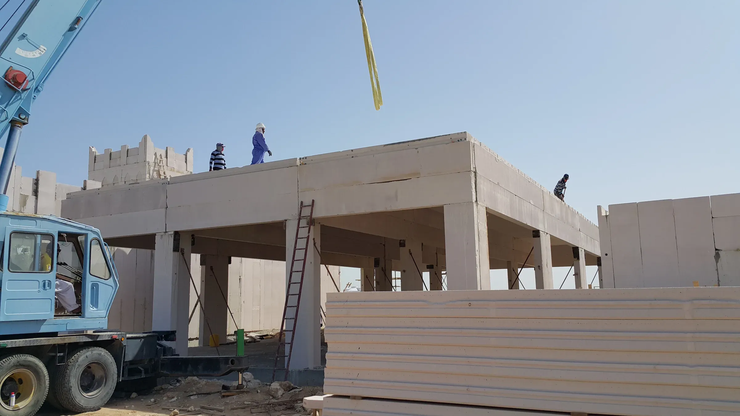
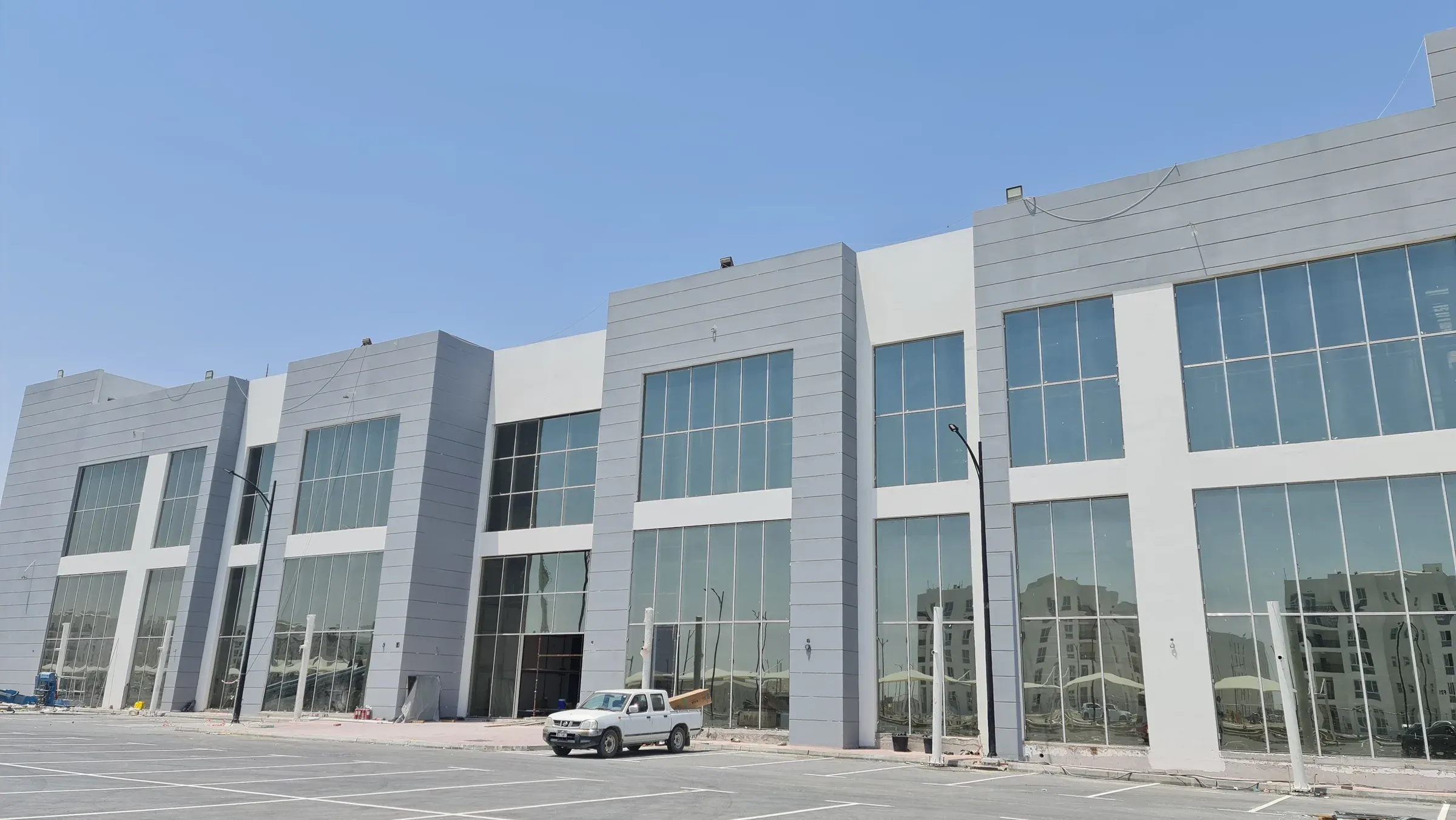
Garages and car parks in AAC walls and roof slabs: light, fire-rated and quick to install.
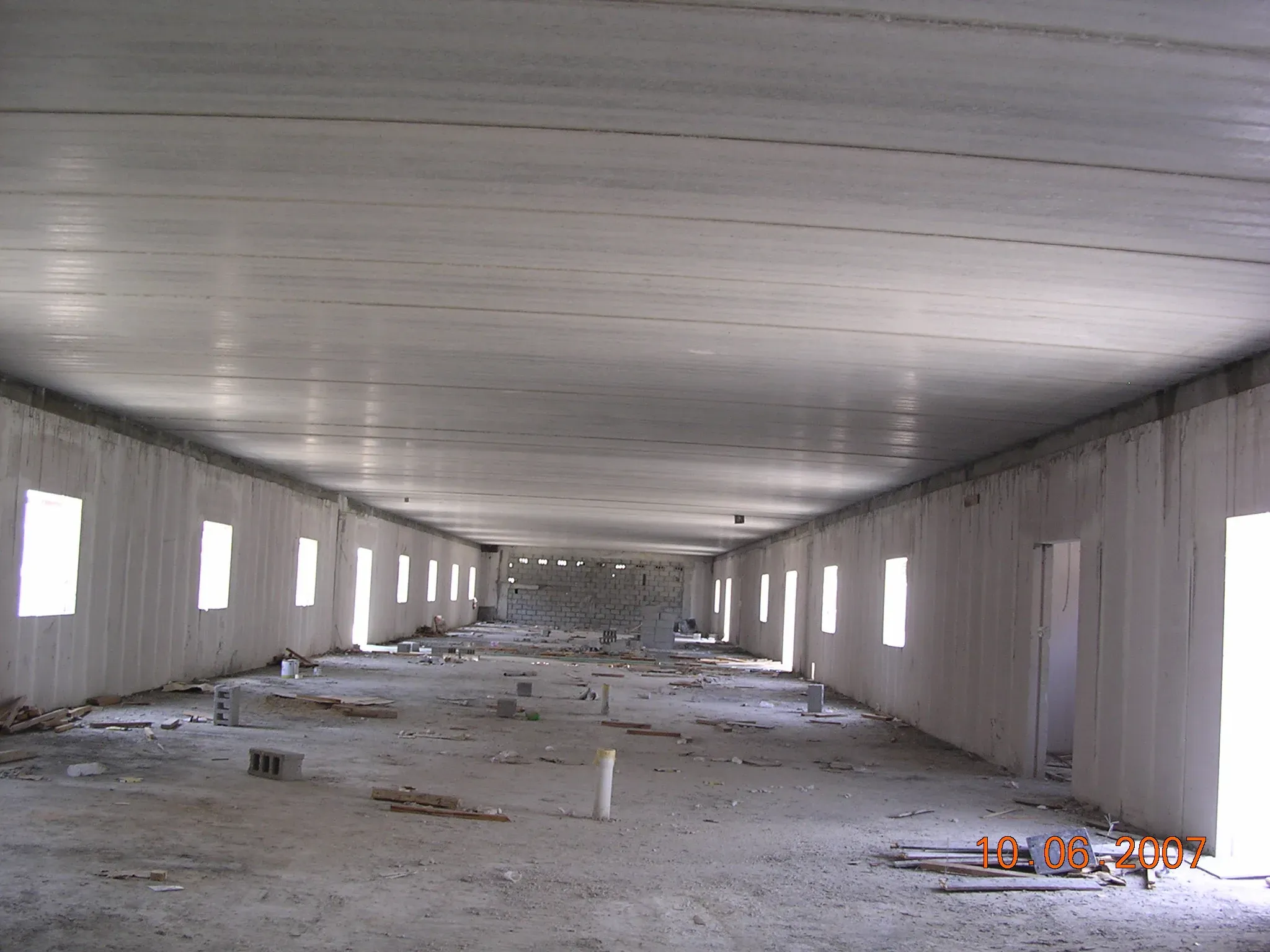
Prestressed hollow-core slabs on AAC wall panels: longer rooms, the same light, fire-rated, insulated walls.
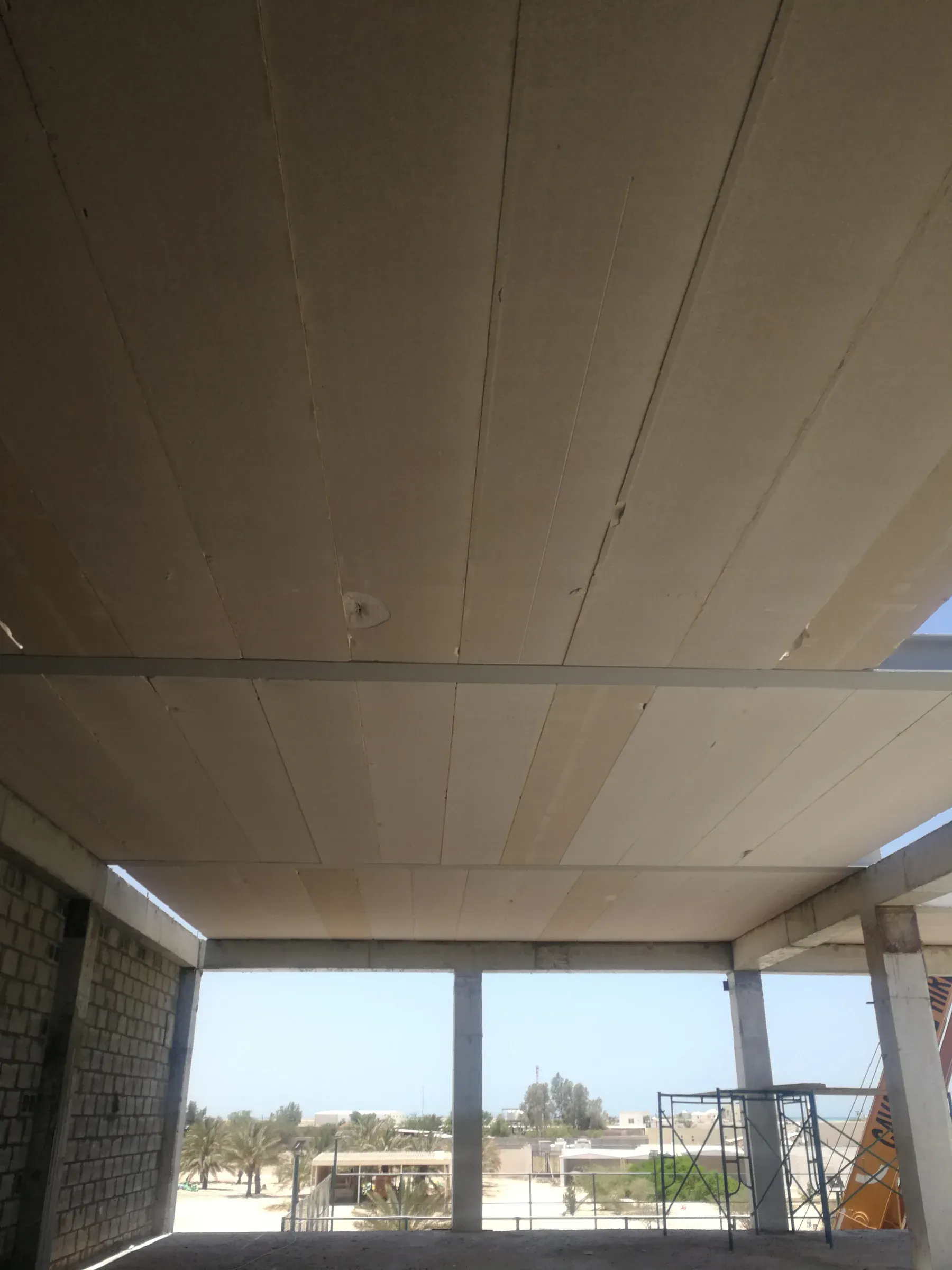
Reinforced AAC roof slabs on any wall: 6 m spans, direct-paint ceilings, insulation built in.
Quartz sand, cement, lime and a trace of aluminium, steam-cured into a cellular silicate with millions of air pores. Complies with DIN EN 12602 for prefabricated reinforced AAC components.
Quartz sand, cement, lime, gypsum and water, dosed by weight.
Welded steel mesh, anti-corrosion coated, set in the mould for each panel.
Aluminium paste is added and the slurry cast around the cages.
Millions of pores form; the cake rises and sets in a few hours.
The green cake is wire-cut to length, width and thickness.
Steam-cured under pressure into a calcium silicate structure.
Panels inspected, banded on pallets and loaded for site.
Nine steps from the pallet to the finished wall, by our own crews with crane or robot. Shop drawings, method statements and typical details are issued for each project.
Panels lifted off the pallet and moved to each wall location by crane or robot.
Wall lines and panel positions set out on the slab from the approved shop drawings.
A bed of AAC glue is laid along the marked wall line.
Each panel is stood, plumbed and pushed home.
The tongue-and-groove joint is glued; the panel is braced until the row is complete.
Wall erection continues panel by panel as per the layout.
Lintels go over the openings; floor and roof slabs are set by crane on the finished walls.
All mechanical fixings are hidden: no visible screws, dowels or bolts.
Polymer putty and coating, paint, tiles, cladding or any other finish.
The AAC System catalogue carries the technical data, design rules, installation method and typical details. Tell us about the project and it comes with the reply.